Quick Release System
New: Flying Wires
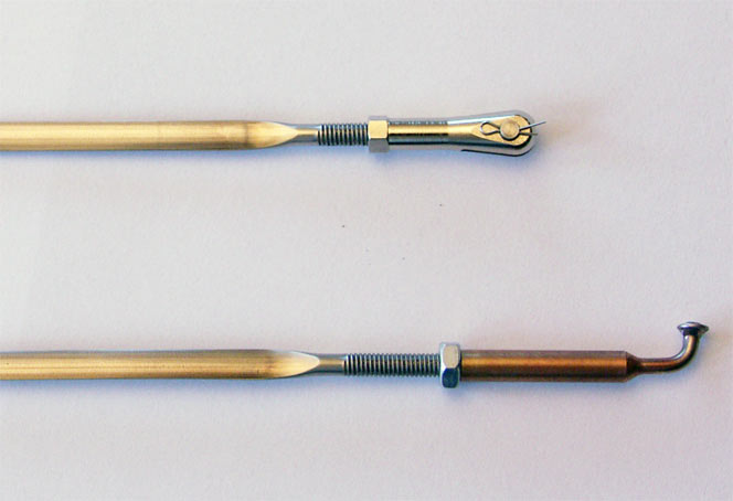
quick-release mounting system for invisible clevises
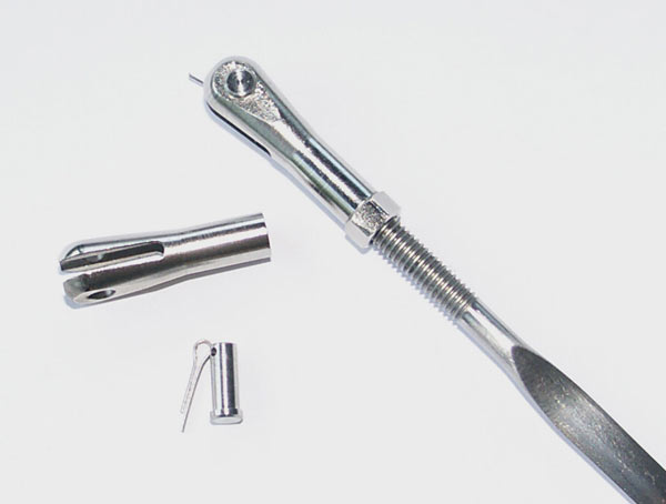
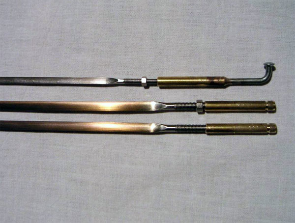
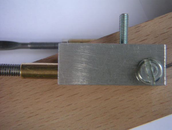
The quick-mounting system consists of the inner end of a motorbike spoke, which is silversoldered into a brass coupling featuring a left- or righthand thread. This spoke is engaged in a keyhole slot of a steel sheet bracket, which is mounted to the spar. The steel bracket is not available as standard as this is very individual.
Mounting procedure:
The landing wires are to be engaged first in the keyhole slots (they have to be sufficiently elongated by relaxing the jamnuts and turning the wire) and then they are slightly tightened and the jamnuts locked.
This setting is to be made only once and must no more be altered unless for trimming puposes.
Then the lift wires (also sufficiently elongated) are engaged in their keyholes and then carefully tensionned by turning the wire. Then the jamnuts have to be locked. It is essentiell that the jamnuts protrude fro the wing surface that they are accessible.
Demounting procedure:
The jamnuts of the lift wires are relaxed and the wires sufficiently elongated (about 4 to 5mm) to enable the demounting of the wires. When lifting the model at the lower wing tips the landing wires can also be disconnected though the flexibility of the wing.
Proposal for a simplified mounting/demounting:
The steel brackets for attachement of the lift wires on the left and right side of the fuselage have to be connected by means of a flexible steel rope and a large turnbuckle located in the belly of the fuselage. This turnbuckle must be accessible through a removable hatch. The front and rear wire system can be tensionned or relaxed by means of a turnbuckle each. With this methode there is no need to alter the settings of the rigging wires.
This methode needs to be implemented right at the beginning of the model’s construction!
Prices upon request. Cost can be saved when silversoldering of the terminals is executed on your behalf.
Description of a simplified version of the Flying Wire Quick-Release system
for scale model aircraft like Pitts or Christen Eagle
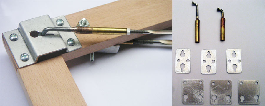
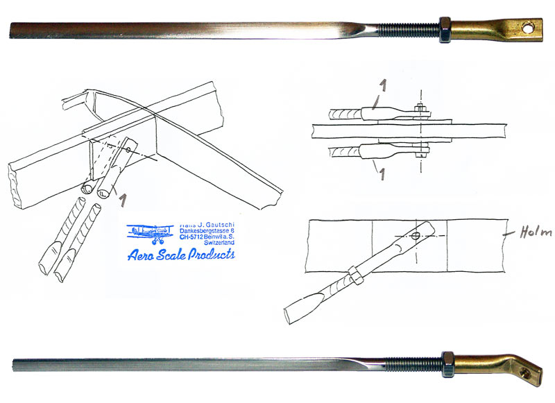
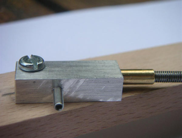
The twin landing wires are secured to the wing spar near the cabane by means of two threaded tubes (Pos 1). The tubes are located on each side of the spar and secured permanently by a joining M3 bolt.
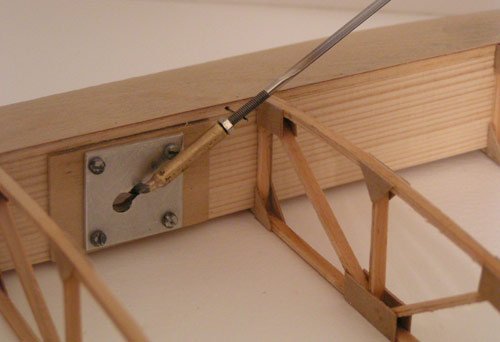
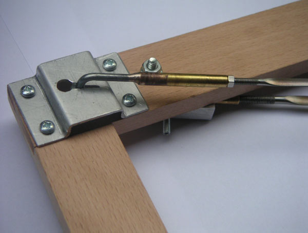
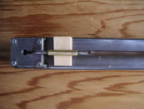
The orientation of the wires is to be given by a rough gide (wooden scrap piece glued along the threaded tubes. This ensures that the wires can be removed from that anchor by turning them while the tubes remain on the spar. Upon dismantling the aircraft for transportation, the landing wires remain secured by jam-nuts at the upper planes. On the other end of the landing wires a quick-release terminal (lefthand threaded with a spoked wire end) is screwed on and engages in a slotted sheet metal bracket secured to the spar (see photo).
When assemblying the model, the upper wing is mounted first (with landing wires installed) to the cabanes.
Then the bottom wing is mounted to the fuselage (while the outer wing struts remain unmounted to eighter wing. Due to the flexibility of the bottom plane, the latter can be slightly lifted in order that the wire’s spocked end can be engaged in the slotted metal bracket.
Now the plane stands on it’s gear, the landing wires are engaged and the lift wires are hanging from the top plane. The lift wires are secured permanently to the top wing spars near the interplane struts by means of threaded tubes in the same manner as the bottom wing. Also here the wires can be unscrewed from the threaded tubes, which remain permanently in the wing.
Now it’s time to install the interplane struts. After this the landing wires are adjusted by turning them (due to left- and righthand threads). Once the correct adjustment is found, the landing wires’ length will no more have to be changed and the jam-nuts can be permanently locked and secured by a small drop of Loctite!
The threaded tubes (Pos 1) at the bottom end of the lift wires also are righthand threaded. Lefthand threads are not necessary, as the lift wires’ lenght has not to be fine tuned. The correct position of the lower threaded tubes is found the first time by screwing or unscrewing them in a loose stage. Also when the correct position is once found, there is no need to change that and the jam-nuts can be permanently locked.
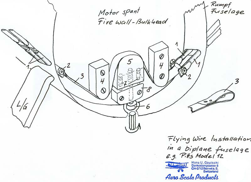
According to the sketch included on both sides the lift wires’s end pieces are being fed into the guiding slots in the fuselage’s side wall.
A thin springsteel band or a flexible hightech-fibreband (Pos 3) with sloped ends is connected to the treaded tubes by means of a bolt and nut. To avoid slipping in the final position a short piece of sandingfabric is glued to the band. To this moment the tensioning device (Pos 5, 6, 7 and 8) is loose.
The tensioning device can be made from plywood (Pos 5) and aluminium (Pos 8). Pos 5 is guided on Pos 8 be means of two steel wires (Pos 7) and the tensioning is executed by turning a steel bolt (Pos 6) which is threaded in the aluminium block. Two blocks made from plywood (Pos 4) serve as a guide for the steel band.
When everything is connected, the rigging is being tensioned by turning the bolt (Pos 6) up to the desired position.
It is recommended that this method of installation is taken as a guide for the individual builder. On special request the shown elements (other than the regularly available quick-release and threaded tubes) can be custom made to your requirements.
If on your aircraft AN type clevises are visible, it is of course possible to replace the threaded tubes by regularly available scale clevises. The aim of this economic installation device is to create an inexpensive wire’s installation while omitting the rel. expensive scale clevises where they aren’t visible anyway.
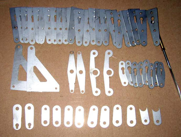
Samples
Demonstration Video

![]()